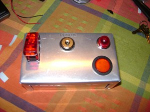
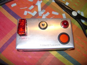
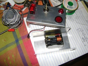
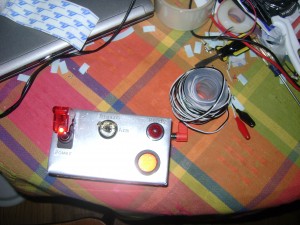
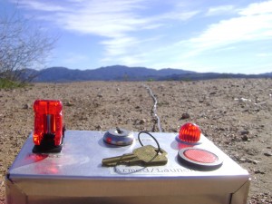
This is the story of my five year old son’s Christmas present.
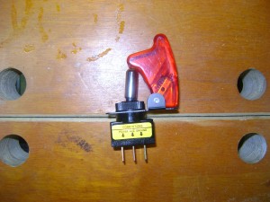
It all started with a trip to Radio Shack. I was looking for a few components for a project and as I was digging through the parts drawers, my son was exploring the drawers below. In the process he found a switch and fell in love. It was the best switch he had ever seen and he wanted it!
We went ahead and purchased the switch for him and when it came time to decide what kind of present to make him this year, I decided that whatever I made had to do justice to this switch… But what should I make?
Looking at the switch, it was clear it needed to control something dangerous like explosives, or a rocket… Since there aren’t many safe ways to play with explosives, I decided a rocket launch controller would be the best, but I definitely needed some parts at least as cool as it.
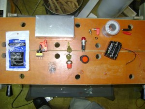
A good rocket controller needs a safety key, and the coolest way to do that is a real key, so I pulled an old key switch out of the garage. I found a battery pack and project box at All Electronics, a light fixture and recessed button at Apex Electronics and picked up some alligator clips, intercom wire, RCA jack and RCA connector at Radio Shack. I also picked up some extra rocket igniters for testing.
The recessed button was a pleasant surprise. Not only is it the “big red button” that I was hoping for since it’s flush with the surface at rest and must be pressed a decent distance into it’s housing to fire, it makes a good safety feature. Also it has a lamp inside, which will allow it to function as a nice “armed” indicator… Besides any self-respecting big red button should glow when it is armed. Since it’s rated at 250 VAC, the voltages we will be using aren’t going to make it very bright, so we are going to want a lamp that will be easier to see in the daylight for our rocket continuity check.
I picked the lamp fixture for that 1980 Hollywood military control center feel. It fits a standard sized bayonet lamp so it will leave us lots of choices as to the exact rating of the bulb. The RCA jacks will allow us to keep the wire seperate from the controller. Desoldering and replaceing wires when they are damaged isn’t my idea of fun, so I’d rather keep the cable seperate from the controller itself.
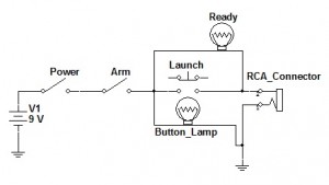
One thing I haven’t mentioned so far: no matter how cool it looks, it’s not much good if it doesn’t work! So let’s think about what exactly we want it to do.
- The switch my son picked out should be the main power switch.
- Nothing should work unless the key is armed.
- Any time the system is armed, the launch button should glow.
- When armed, the ready lamp should glow only if there is a circuit through the igniter.
- The rocket shouldn’t launch until the launch button is pressed (mis-fires can be bad things).
So the basic circuit should look something like this:
This circuit should give us the behavior we want, but what about part ratings? First we need to look at the ratings for the igniter we are going to use. The igniter package gives these three numbers:
Maximum no fire current: 500mA
Minimum all-fire current: 2A
Igniter resistance including lead wires: 0.6904Ω
So this means that our ready lamp must not draw more than 500mA and we need to be able to source more than 2A to the 0.6904Ω load. Given that our battery pack is made up of 6 AA batteries in series, we’ll be operating at 9V, so this means the max current that could go through the load is given by Ohm’s Law:
9V/0.6904Ω~13A
The actual current will be limited by what a single AA can generate, but that is the maximum current that could occur. The ready lamp will need a high enough resistance to prevent a mis-fire:
9V/0.5A=18Ω (or higher, in our case)
I hunted around for a while until I found the right lamp for the job. It needed a high enough resistance to prevent firing, but also glow brightly at the provided voltage. The lamp I selected was the #1815 Miniature Bayonet Lamp. This lamp is rated for 14V at 200mA giving it a resistance that is definitly high enough for our purposes, keeping the current well below the maximum rating:
14V/0.2A=70Ω
9V/70Ω~129mA
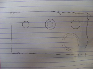
It looks like I have everything I need, so the first step will be to decide where I want the parts on the project box, and drill the holes. First I quickly traced the top of the box and then outlined the parts where I wanted them on the panel. I used some calipers to measure the actual size of the component bodies and drew those cicles inside with a compass. The final template looked like this:
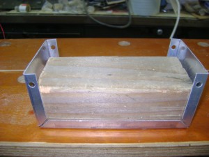
I cut the center out of each circle to trace onto the project box, but first I needed a way to keep the metal from bending while I drill the holes. I decided to put a block of wood inside of the project box to provide support:
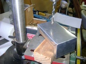
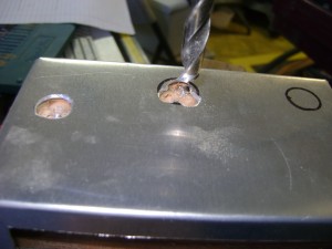
I traced the circles onto the box and started drilling. The first hole went very smoothly, but soon I had to get more creative. Some holes needed to be larger than any of my drill bits, and one needed to have flat sides. It turns out there is a simple trick to handling this. Drill several holes with a smaller bit, then finish it off with a file:
The flat sides on this hole keep the key switch from rotating when you turn the key:
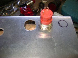
When I was done drilling the holes I had a bunch of somewhat ragged holes in a chunk of alluminum. I was worried that this project wouldn’t look so good, until I inserted the actual components. It turns out all the raggedness and scuffing stayed within the area the components overlap with the case!
The one label looked so good, I added a full complement:
I didn’t want the battery pack bouncing around in there bending pins and ripping out wires, so a little velcro seemed to be in order:
You can see I’ve attached the RCA connecter and allegator clips to the intercom wire, now it’s time for a quick light test!
And launch time!
The rocket ignited as expected, the one note I have is “remember to hold the launch button until it’s fully burned out”. It can take a few seconds for the igniter to completely start and half burning it with a quick press may not start it, and may consume it too much to try again.
My son was incredibly happy with the project and plans to use this controller on all of our future rockets!
